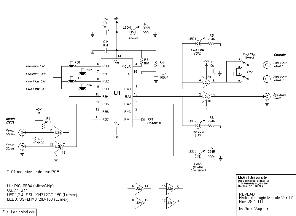

This schematic is also available in CDR v.9 format and PDF format

The CDR v.9 file used to make this template is: faceplate.cdr
To operate this module:
Assume also that:
When the Pressure ON button is depressed, the PRESSURE O/P is activated (goes high). This indirectly activates the pressure valve which builds up pressure in the accumulator. Verify that the pressure in the accumulator has reached the maximum level (as set on the pump) by reading the gauge in the hydraulic cabinet.When the FWD Flow ON button is depressed, either the FWD FLOW 1 (supine ankle setup) or 2 (standing ankle setup) O/P is activated (high) depending on the position of the SEL toggle switch. The ON buttons must be depressed in the sequence described above.
The Oops! LED lights up when an illegal operation has been performed. To clear this condition, depress the PRESSURE OFF and FWD FLOW OFF buttons simultaneously.(Turning the pump off and back on will have the same effect, but this is not the recommended method.)
When power is first applied to this module the PIC microcontroller goes through a power-up sequence. (The duration of the power-on-reset varies between 28-132 ms. This excludes other factors such as oscillator start-up time that will only lengthen this period.) During that time frame the outputs of the module are undefined and equipment under control may be subjected to transients. Hence, it is recommended that this module be powered up prior to equipment under its control.
Standby mode: Once forward flow has been established, depressing the FWD Flow OFF button stops fluid flow to the actuator and places the system in a standby mode. Depressing the Pressure OFF button instead generates an Oops! to remind the user that pressure needs to be built-up in the accumulator before forward flow may be re-established.
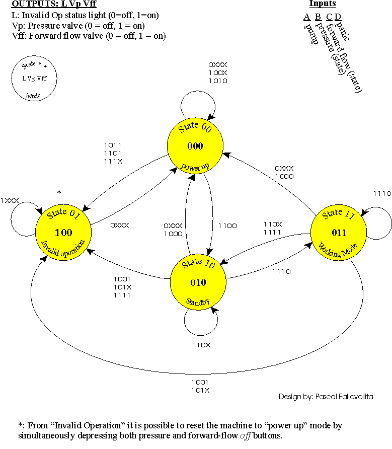
The state-transition diagram below describes the operation of the logic module under all input conditions. When the module powers-up the machine starts at state 00, in which all outputs are low. For example, in a normal hydraulic start-up sequence the state machine would transition as follows: Power up -> Standby (pressure valve on) -> Working Mode (pressure and forward flow valves on). A panic condition would then change the state to Invalid Operation (all valves off but Oops! light on). Note that panic conditions are context sensitive and do not always set the state to Invalid operation. Shutting off the pump, however, always resets the state to Power up.

This diagram is also available in CDR v.9 format and PDF format
The state transition table (available in

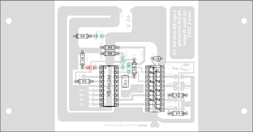
In order to make new printed circuit boards, use this template: pcb.pdf. Alternatively, this diagram can be found in the logicmod.cdr file above (see Schematic).
Last modified: 29 November 2001, Laura Galiana