Hydraulics Tutorial
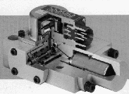
Servo-controlled hydraulic systems provide exceptional control over very large forces. The most critical element of the system is the electrohydraulic controller or servo. Common servo-valves consist of a two stage spool whose position is controlled by electromagnetic coils (figure 1). Energizing the coils allows fluid flow (which translates as a velocity in actuator movement) in one direction or the other depending on the input signal.
Tolerances for the spools are very close, and servo valves should always be handled with extreme care. Replacement of a servo-valve will cost approximately $2000 while re-spooling (a servo equivalent of an engine rebuild) is still expensive at about $400. In order to avoid any damage due to ignorance, this document prepares the user for proper care and installation of the hydraulic equipment related to servo-valve controlled systems. This advice is a compilation of conversations with manufacturers, hydraulic specialists and from hard experience.
Flushing
The golden rule of servo safety is cleanliness. Never assume anything is clean enough until you prove it. Any disassembly or modifications to the hydraulic system between the filter and servo-valve calls for a full scale flushing operation described below. This discussion assumes a fully functional system complete with appropriate filters already in place. In order to properly flush such a system, a two stage procedure should be followed. For stage 1, disconnect the high and low pressure connections from the actuator manifold. Take care to identify pressure and return lines (marked P and R or High and Low) for re-assembly. Connect the pressure and return lines by means of an appropriate fitting (JIC #12 on the high pressure systems). Activate the hydraulic pump and allow fluid to flow. This is the equivalent of an electrical short circuit and allows the entire pump capacity to flow through the (possibly) contaminated lines. Allow fluid to flow for at least 30 minutes and preferably 2 hours. Once this has been done, disconnect the high and low pressure lines and re-attach to the actuator manifold (make sure that the hoses are appropriately attached).
To complete the flushing, stage 2 requires removal of the whole servo-valve assembly (not just the first stage). This assembly is illustrated in figure 2 (use a 3/16 allen key, NOT the 3/32 for the Dyval for example). Replace the servo-valve with the flushing plate supplied with each valve (plain aluminum with the Moog and anodized aluminum with a lever for the Dyval). Tighten opposite screws moderately to prevent leakage. There is no need to over-tighten: O-rings work well under normal pressure (as long as they arenŐt on the Challenger) and they, not the screws, keep the oil in. Place the shipping plate (formerly attached to each flushing plate) on the servo to keep dust and small particles from entering the servo while flushing. Fix the rotary actuator (mechanical stops, not only the hydraulic stop) in one spot or, for the linear actuator, place the lever in mid-position. Activate the hydraulic pump once again and allow fluid to flow through the manifold, hoses and filter assembly for a minimum of 4 hours. In the case of the linear actuator, operate the hand lever from side to side 20-50 times over the 4 hour session. The cylinder should move from one extreme position to the other. Install a cushion (tubing works well) to prevent damage to the cylinder during this procedure. Once this has been accomplished, re-install the servo-valve (make sure surfaces are clean) and tighten opposite mounting bolts moderately. Over-tightening may cause the spool to bind, with unpleasant consequences.
Keep all surfaces reasonably clean, follow these guidelines and you should have clean hydraulic fluid at this stage. Over-flusing a system will never hurt it, some people have recommended up to 20 hours of flushing to properly clean a new system.
Filters
Filters are part of any hydraulic system and serve to keep a system functional by trapping any harmful particles before they reach the servo-valve. Moog #071-60645 filters are so-called 3 micron filters, designed specifically for use in servo operations. The servo-valves in use in the lab quote ISO 14/11 as a preferred state of cleanliness an a maximum of 16/13 (see Measuring Hydraulic-Fluid Contamination).
The state of the filters is monitored by an electronic interrupt which is activated when delta-P across the filter approaches the total delta-P in the system (standard delta-P is 20 psi or so). Care must be taken when handling the new filter during installation to avoid contamination due to handling (dirty hands etc.).
- Removal of the old filter is easy:
- unscrew the aluminum housing and remove the filter hanging there. (Be aware that there is fluid in the filter - don't turn it upside down without being prepared).
- Remove the new filter from its box and carefully slit the plastic around the top. To avoid filter damage, do not slit the plastic over the filter element!
- Install by pressing the mating surfaces together and seating the O ring assembly
- re-install the aluminum casing
- DO NOT put the filter in the casing and then screw on. This is a recipe for disaster as the O-rings may never mate properly and fluid will happily flow around the filter rather than through it.
- Note that any time you replace a filter, you MUST flush the system (stage 2 at least) before use.
