Servo-Valve Module
Functional Description
Brief Description: This module is used for driving the servo-valve. The voltage input is converted to a current output to drive the servo-motor. This module also provides a current source on the front panel. Essentially this module is a voltage to current converter and is used to drive servo-valves.
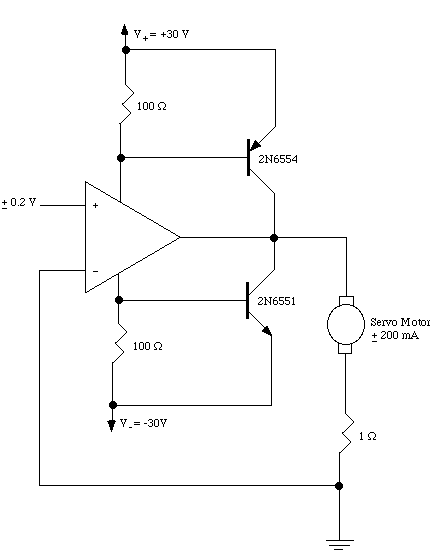
The schematic of a typical Servo Amplifier is presented below. To enlarge the schematic, click on it.
This schematic gives an example of a circuit for a Servo-Motor Amplifier. The circuit shown here is a 0.2 Amp Servo-Motor Amplifier. The power source used in this case is +/- 30 Volts.
Front Panel
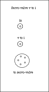
Front Panel of Servo Amplifier
Module
Inputs:
One input, V1, is applied by the BNC connector on the front panel.
Outputs:
Two outputs channels are provided on the output. One is for driving the servo-motor. The second is a current source (v to i).
Circuit Diagram
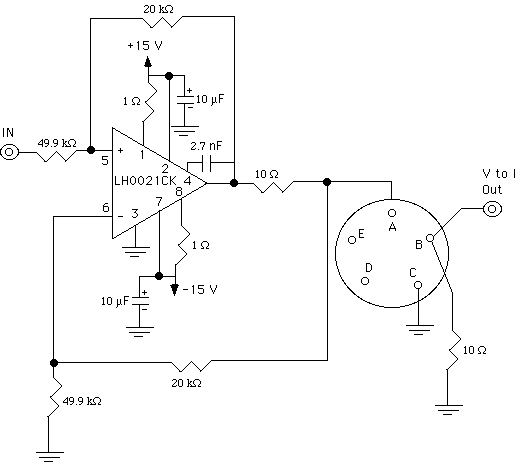
Servo Amplifier Module Schematic
The figure above shows the schematic of the Servo Amplifier Module used in this lab.
Operation
To input the desired voltage to drive the servo-motor connect a BNC connector to the input channel marked in. The desired output driving current is set by the user selecting the input voltage to this module.
List of Components
· 1 LH0021CK Operational Amplifier
· Dielectric Capacitors
· +/- 10% Resistors
· 1 Circular connector (Cannon)
Functional Specifications
This module requires +/- 15 Volt power supply to operate.
The Current Output levels for this module are:
|
Input Voltage Volts (DC) |
Output Current Amps (DC) |
|
0 - 3.99 |
0.00 |
|
4 - 9.99 |
-0.01 |
|
10 - 15 |
-0.02 |
