| Common apparatus |
|---|
| Hydraulic system |
| Electronic components |
| Data acquisition |
| EMG monitoring |
| NLID Tools |
| Troubleshooting |
| Materials |
| Supine apparatus |
|---|
| Assembly procedure |
| Safety Measures |
| Components |
| Servovalve |
| Actuator |
| Potentiometer |
| Pressure Filter |
| Torque transducer |
| Boot |
| Literature |
| Computing resources |
|---|
| CVS |
| Ethics |
|---|
| SDS / Inventory |
|---|
Offset-Gain module
Schematic
This diagram is also available in CDR v.9.0 (OffsetGain.cdr) or in pdf format (OffsertGain.pdf)
Components:
- resistors
- LT1007 operational amplifiers
- LT1001 operational amplifier
- Variable resistors
- REF 01 reference voltage source
- BNC connectors
- SPDT switches
Functional description
faceplate.cdr: CorelDRAW 9.0 file used to make faceplates
This module is used to adjust the gain of two inputs and ouptut their sum. The same output can be viewed on each of the OUT BNCs.The input is selected with a switch selected as:
- NORM: input is connected to IN BNC
- 0 V: input is grounded and disconnected from input BNC
- 1 V: input is connected to a 1 Volt reference output.
The rotary gain switch varies the gain multiplier from 0.01 to 1000 by using the following resistors:
|
Switch position |
Gain |
Resistance (ohms) |
|
-2 |
0.01 |
10 |
|
-1 |
0.1 |
100 |
|
0 |
1 |
1K |
|
1 |
10 |
10 K |
|
2 |
100 |
100 K |
|
3 |
1000 |
1 M |
The gain trim potentiometer adjusts the gain by a scale factor ranging from +1 to 1.Therefore Vout=(V1*Gswitch*Gadj)+(V2*Gswitch*Gadj). One channel can be used as an offset by setting its input to 1 volt and adjusting the gain switch and gain adjust to a desired offset value. In this case, Vout=(V1*Gswitch*Gadj)+offset2.
In order to set the gains, follow this procedure:
- set switch 1 to 1 V and switch 2 to 0V
- adjust the gain of channel 1
- set swtich 1 to 0V and switch 2 to 1V
- adjust the gain of channel 2
- set switch 1 to NORM and switch 2 to NORM
- you now have the summed output of the two channels, Vout.
|
Switch 1 |
Switch 2 |
Output (adjusted with gain) |
|
NORM |
0V |
Input 1*G1 |
|
NORM |
1 V |
Input 1*G1+ 1 volt*G2 |
|
NORM |
NORM |
Input 1*G1 + Input 2*G2 |
|
0V |
0V |
0 volt |
|
0V |
1 V |
1 volt*G2 |
|
0V |
NORM |
Input 2*G2 |
|
1 V |
0V |
1 volt*G1 |
|
1 V |
1 V |
1 volt*G1+1 volt*G2 |
|
1 V |
NORM |
1 volt*G1+Input 2*G2 |
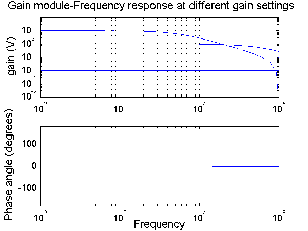
Frequency response
The frequency response shows that for gains from 0.01 to 10 the gain response is quite flat. There is a small roll-off at 50 000 Hz at a gain setting of 100. At a gain setting of 1000 the roll-off is much steeper and begins at 5 000 Hz. The phase shift is flat at 0 degrees for all gain settings.
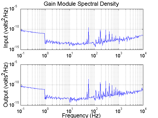
Noise Analysis
The noise output of this module was very low.
Last Modified: November 30, 2001 Laura Galiana