| Common apparatus |
|---|
| Hydraulic system |
| Electronic components |
| Data acquisition |
| EMG monitoring |
| NLID Tools |
| Troubleshooting |
| Materials |
| Supine apparatus |
|---|
| Assembly procedure |
| Safety Measures |
| Components |
| Servovalve |
| Actuator |
| Potentiometer |
| Pressure Filter |
| Torque transducer |
| Boot |
| Literature |
| Computing resources |
|---|
| CVS |
| Ethics |
|---|
| SDS / Inventory |
|---|
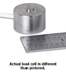
Load Cell - standing
 The
Omega™ LC302-100 is a 0.75" diameter stainless steel compression
load cell, with 0-100lb capacity.
The
Omega™ LC302-100 is a 0.75" diameter stainless steel compression
load cell, with 0-100lb capacity.
Each pedal on the apparatus is equipped with four such load cells, one near each corner, which allows one to measure the total weight on the pedal as well as the center of pressure. (See remarks below regarding limitations.)
The cells have an absolute maximum rating as to the amount of force that
may be applied before being damaged. As such, people must step on and
off of a pedal with care.
- Specifications
- Factory calibrations (Scanned)
Limitations
The load cell reading is true only when the force applied is perpendicular to the surface area of the load button. Hence, measurements are accurate only when the pedal is in a horizontal position.
Interfacing
A load cell is interfaced to a strain gage conditioner module. Each module needs to be calibrated with a uniquely associated load cell.
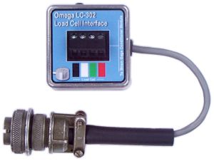 For testing an individual load cell on a work bench use this interface
box to be able to connect the cell to a strain gage conditioner module.
For testing an individual load cell on a work bench use this interface
box to be able to connect the cell to a strain gage conditioner module.
The layout for this box may be found in this
Corel DRAW 9 file.
Strain Gage Module Calibration
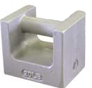 The
lab has two 50-lb (+/- 2.3 g), Class F, Type II Troemner grip
handle weights. The idea was to stack the weights onto a load cell
and calibrate the strain gage conditioner to read 10V/100lb. However,
in the absence of a jig to support the weights steadily and squarely on
top of a load cell sway of the weights introduce significant calibration
errors. Hence, the following alternate calibration procedure is used.
The
lab has two 50-lb (+/- 2.3 g), Class F, Type II Troemner grip
handle weights. The idea was to stack the weights onto a load cell
and calibrate the strain gage conditioner to read 10V/100lb. However,
in the absence of a jig to support the weights steadily and squarely on
top of a load cell sway of the weights introduce significant calibration
errors. Hence, the following alternate calibration procedure is used.
The calibration procedure relies on the full-scale factory calibration value of a given load cell and does not require that the transducer be connected to the strain gage conditioner.
- Set the module gain to G = 2000. (Use a zero-mean 10-Hz sine wave as the test signal. Observe the module output on an oscilloscope and adjust the panel-mounted offset trim potentiometer to roughly center the trace about 0V. Measure input and output AC amplitudes using an HP 34401A DMM and set the gain. More stable results will be obtained if the DMM is configured for slow AC filtering.)
- Set the dc excitation voltage, Vexc, to the required value so as to produce the desired output voltage for full-scale (force) input. (Use the factory calibration sheet for the particular load cell. Note that the cell's full-scale ouput, VFSO, is rated at 10Vdc excitation. Hence, if the desired module output is X volts for a 100lb load then the required excitation voltage is Vexc = (10 · X)/(G · VFSO). You will most likely be able to adjust this voltage to 2 decimal places only.)
- Trim the instrumentation amplifer offset to 0V. (Ground the inputs to the module. Monitor the voltage at point S on the printed circuit board. Trim the INPUT OFFSET potentiometer until the measured voltage is near 0V.)
Center of Pressure (COP)
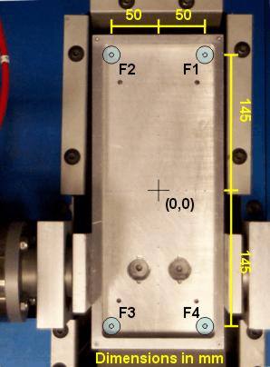 The
figure here shows the left pedal assembly and the positions of the four
load cells; the right pedal is of a similar arrangement. The load cells
are actually sandwiched between the plate and the pedal.
The
figure here shows the left pedal assembly and the positions of the four
load cells; the right pedal is of a similar arrangement. The load cells
are actually sandwiched between the plate and the pedal.
The origin of the center of pressure (COP) is defined to be at the centroid
of the bounding box formed by the cells.
 If Fi is the force
measured by the i-th load cell, then the COP (in mm) is calculated
as follows:
If Fi is the force
measured by the i-th load cell, then the COP (in mm) is calculated
as follows:
Note that the bias on each load cell due to the weight of the pedal (i.e.,
the baseline reading) must first be subtracted from the Fi before
using these equations.
Miscellaneous
 This sign
was produced with this Corel DRAW
9 file.
This sign
was produced with this Corel DRAW
9 file.
Last Modified: 2006-08-23 Ross Wagner