| Common apparatus |
|---|
| Hydraulic system |
| Electronic components |
| Data acquisition |
| EMG monitoring |
| NLID Tools |
| Troubleshooting |
| Materials |
| Supine apparatus |
|---|
| Assembly procedure |
| Safety Measures |
| Components |
| Servovalve |
| Actuator |
| Potentiometer |
| Pressure Filter |
| Torque transducer |
| Boot |
| Literature |
| Computing resources |
|---|
| CVS |
| Ethics |
|---|
| SDS / Inventory |
|---|
Panic Control Module

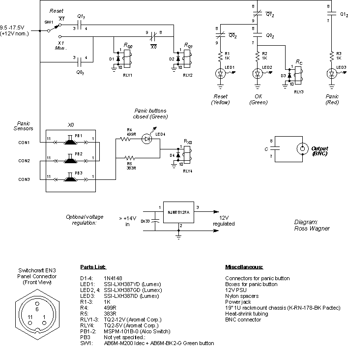
This schematic also available as: panic_control.cdr (v.9), panic_control.pdf
Components
Functional Description
faceplate.cdr: CorelDRAW 9.0 file used to make faceplates.
This module manages three panic buttons used to stop the flow of hydraulic fluid through the actuator(s). If any button is momentarily pressed the panic condition is latched and a signal is sent to the LOGIC MODULE to request that all forward flow valves be turned off.
To operate this module:
- Connect a N/C switch to each of the circular connectors.
Assume also that:
- The "Panic Status Output" is connected to the "PANIC status" I/P of the LOGIC MODULE.
When power is first applied to the module the amber "Press RESET to start" light will be on. Confirm that the "PANIC BUTTONS CLOSED" light is also on; the module will not work unless this light is lit. Press the RESET button to prime the module. The green "OK" light will come on and the amber light will turn off. The PANIC STATUS OUTPUT is a dry-contact relay. In the module's current state this BNC output will read as a short indicating that no panic condition is present. Fluid flow may now be turned on via the LOGIC MODULE.
The tree panic buttons are in series. Should any contact open momentarily a panic condition will be registered and latched. Then the red "Panic button pushed" light will light up (the green light will go off) and the PANIC STATUS OUTPUT will be open-circuit signaling to the LOGIC MODULE that a panic condition is present.
During
the time that a panic button is pressed (open circuit) the PANIC BUTTON CLOSED
light will be off. In order to recover from a panic confirm that the light
is back on and press the RESET button again.
State Diagram
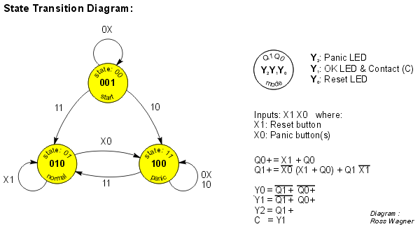
The state-transition diagram below describes the operation of the panic control module under all input conditions. Note that input X1 is active high, whereas input X0 is active low (negative logic).
When the module powers-up the machine starts at state 00, in which the panic LED is off, the OK LED is off, the relay contact is open (relay de-energized), and the reset LED is on. Then, for example, pressing the RESET button while a panic condition is present causes the machine to transition to state 11 (panic), whereby the panic LED is on, the OK LED is off, the relay contact is open, and the reset LED is off. To exit from this state the reset button must be pressed in the absence of a panic condition (X1 = 1, X0 = 1). The state then transitions to 01, the normal operating condition.

This schematic also available in: panic_control.cdr (v.9)
Printed Circuit Board
In order to make new printed cricuit boards, use this template: pcb.pdf. Alternatively, this diagram can be found in the panic_control.cdr file above (see Schematic).
Last modified: February 18, 2002 Laura Galiana

