| Common apparatus |
|---|
| Hydraulic system |
| Electronic components |
| Data acquisition |
| EMG monitoring |
| NLID Tools |
| Troubleshooting |
| Materials |
| Supine apparatus |
|---|
| Assembly procedure |
| Safety Measures |
| Components |
| Servovalve |
| Actuator |
| Potentiometer |
| Pressure Filter |
| Torque transducer |
| Boot |
| Literature |
| Computing resources |
|---|
| CVS |
| Ethics |
|---|
| SDS / Inventory |
|---|
Rectifier/Filter module
This schematic also available as: filt_rect.cdr (v.9), filt_rect.pdf
Components:
- LT 1007 operational amplifier
- AMP-02 instrumentation amplifier
- 1N4148 Diodes
- 711H4B Frequency Devices, 4th-order, Butterworth High-pass filter, fc = 5Hz
Functional Description
 faceplate.cdr:
CorelDRAW 9.0 file used to make faceplates.
faceplate.cdr:
CorelDRAW 9.0 file used to make faceplates.
This module is used to condition an EMG signal with a high pass-filter followed by a full-wave rectifier. The high-pass filter is used to reject low-frequency motion artefacts. The rectified output may be selectively inverted. In our lab, the Tibialis Anterior EMG is positively rectified, whereas the Gastrocnemius EMG is negatively rectified. (The 15-volt output once available to power an EMG pre-amplifier has been discontinued in this module.
The output signal from the EMG amplifier is applied to the input BNC connector on the front panel. If the signal is to be high-pass filtered only, the output should be connected to the NORMAL output BNC and the filter switch placed to ON. If the input is to be rectified only, the ouput has to be connected to the RECTIFIER output BNC and the filter switch must be set to OFF. The rectifier switch can be set to positive or negative rectification. If the output is to be rectified and filtered, the output has to connected to the RECTIFIED output BNC with the filter switch ON. You may also have an output of 15V at the 15V output BNC which can be used to power the EMG amplifier.
The following table summarized the possible outputs:
|
Output |
Filter switch |
Output BNC |
Rectifier switch |
|
HP filtered only |
ON |
Normal |
Not used |
|
Rectified (+/-) only |
OFF |
Rectified |
+ or - |
|
HP filtered and rectified |
ON |
Rectified |
+ or - |
|
15 volts |
Doesnt matter |
15 V |
Not used |
Description of rectifier circuit
R1, R3, D1, D2 and IC2 form an inverting, half-wave precision rectifier with positive-polarity selection. The circuit operates by providing two gains. For a positive input, D1 is reversed biased and D2 is forward biased; resulting in a gain of -R3/R1 = -1. For an input with negative polarity, D1 is forward biased and D2 reversed biased; resulting in a gain of 0/R1 = 0.
R2, R4, R5 and IC3 form an summing amplifier with differing gains along each input branch. A signal travelling along branch R2 is amplified with a gain of -R5/R2 = -1, whereas a signal travelling along branch R4 is amplified with a gain of -R5/R4 = -2.
IC2 and IC3 together form a non-inverting, full-wave precision rectifier. The circuit operates by adding the raw signal provided by SW1 to twice the output of IC2, and inverting it. As such, positive portions of a signal, say, x are processed as follows: -(x + 2(-x)) = x. Negative portions of the signal, on the other hand, are processed as follows: -(x + 2(0*x)) = |x|. Hence, the output of IC3 is always positive.
R7, R8 and IC4 form an inverting amplifier with negative unity gain. It is used to provide an inverted rectified output via SW2. C1, R6, C2 and R9 compensate their respective OpAmps so that large capacitive loads may be driven (e.g, long cables). This form of compensation does not reduce phase margin but may only be used on OpAmps that are stable at unity gain.
Printed Circuit Board
In order to make new printed cricuit boards, use this template: pcb.pdf. Alternatively, this diagram can be found in the filt_rect.cdr file above (see Schematic).
Noise analysis
Filter:
The output noise of the filter was very low.
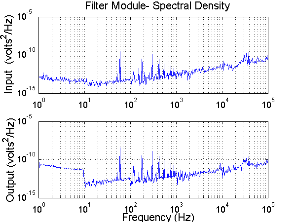
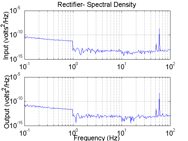
Rectifier:
The output noise of the rectifier was very low.
Last modified: November 30, 2001 Laura Galiana