| Common apparatus |
|---|
| Hydraulic system |
| Electronic components |
| Data acquisition |
| EMG monitoring |
| NLID Tools |
| Troubleshooting |
| Materials |
| Supine apparatus |
|---|
| Assembly procedure |
| Safety Measures |
| Components |
| Servovalve |
| Actuator |
| Potentiometer |
| Pressure Filter |
| Torque transducer |
| Boot |
| Literature |
| Computing resources |
|---|
| CVS |
| Ethics |
|---|
| SDS / Inventory |
|---|
Servo-Valve Module III
Schematic
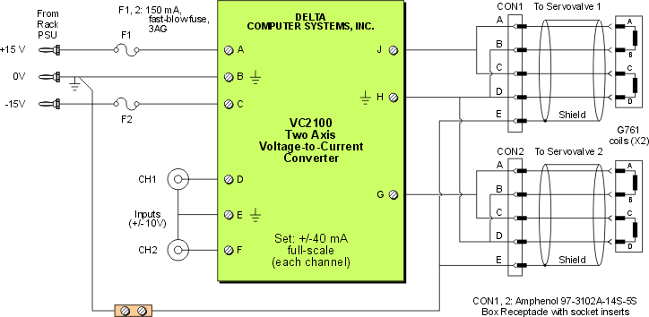
Schematic available in Corel DRAW9 format and PDF.
Components
- DELTA Computer Systems VC2100 V/I Converter
- 150 mA, fast-blow, 3AG fuse (Littlefuse P/N 312.150P) (X2)
- Littelfuse low profile fuse holder (P/N 3453LS1) (X2)
- Amphenol box receptacle with 5 socket inserts (X2)
- DIN rail
Functional Description
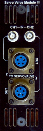
Faceplate available in CorelDraw9 file: faceplate.cdr
This module is a voltage-to-current converter that is used to drive the servovalves on the standing apparatus.
For each channel:
Input voltage range: +/- 10V
Output current: 4 mA/V
Maximum output current: 40 mA
Each G761 servovalve contains two coils. (See above schematic.) This module drives the pair of coils in parallel.
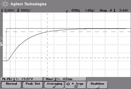
Step Response
The typical step response of a channel to an input amplitude of ~20 V into a 25-ohm is shown below. The 10-90% risetime is ~ 430-445 us. Both channels have similar characteristics. (Test date: April 18, 2007.)
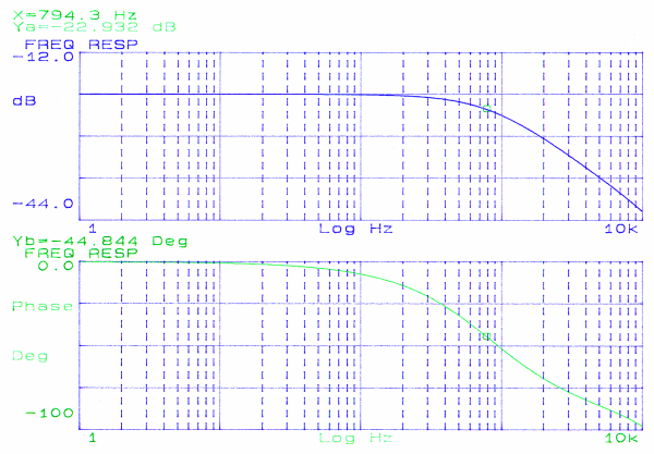
Frequency Response
The typical frequency response of a channel is shown below and was measured using an HP dynamic signal analyzer. Performacne was determined using a swept sinusoid of 5 Vpk (the maximum amplitude that the analyzer could generate) into a 25-ohm load. The result shown is for CH1. Similar results were obtained when the excitation was decreased to 500 mVpk. Similar results for CH2. Cut-off frequency ~800 Hz. (Test date: April 18, 2007.)
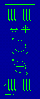
CAM files
The component mounting holes for the front and back faceplates may be machined on a prepared faceplate base using these Mastercam X files:
- Front faceplate (247 KB)
- Back faceplate (328 KB)
 |
 |
Last modified: 2007-05-14 Ross Wagner