| Common apparatus |
|---|
| Hydraulic system |
| Electronic components |
| Data acquisition |
| EMG monitoring |
| NLID Tools |
| Troubleshooting |
| Materials |
| Supine apparatus |
|---|
| Assembly procedure |
| Safety Measures |
| Components |
| Servovalve |
| Actuator |
| Potentiometer |
| Pressure Filter |
| Torque transducer |
| Boot |
| Literature |
| Computing resources |
|---|
| CVS |
| Ethics |
|---|
| SDS / Inventory |
|---|
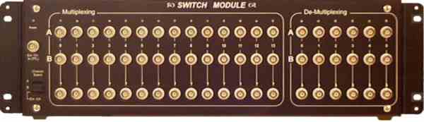
Switch Module
This schematic also available as:switch_module.cdr (v.9), switch_module.pdf
Components
- 2N3904 NPN transistor
- 2N3906 PNP transistor
- 1N4148 diode
- MCL-934SGC LED (Multicomp)
- 2599 LED panel mounts (Multicomp)
- RMCS190513BK1 chassis (Hammond Enclosure)
- 19211-003 Wire pin terminals (GC/Waldom)
- 50-57-9002 2-circuit connector housing (Molex)
- 16-02-0097 C-Grip box crimp terminals (Molex)
ERB-24 Keithley Instruments relay board
Functional Description
faceplate.cdr: CorelDRAW 9.0 file used to make faceplates.
(The faceplate was printed at MP Photo Reproductions on a 3M adhesive-backed vinyl. The media is soft and delicate. Consequently, it is easily susceptible to nicks and deep scratches. Care must be exercised when tightening panel components as excessive pressure on the vinyl will cause it to warp and bubble around the component.)
This module provides a bank of 2:1 analog multiplexers and a bank of 1:2 analog de-multiplexers in order to allow sharing of data acquisition equipment between two experimental setups. The MUX and De-MUX ports are setup as follows:
Note that all signals are floating with respect to ground.
Signal routing is determined by the position of the "Channel Select" switch. When channel A is selected annunciator LEDs above the channel BNCs become illuminated. When "Ext. Ctrl." is chosen channel selection is determined by an external TTL signal; a high level selects channel A.
For convenience, each multiplexer port output and each de-multiplexer port input is duplicated on the back panel. Regarding the de-multiplexer input connectors, do not apply different signals to both front-panel and rear-panel connectors simultaneously.
Port/relay assignments are listed in the following documents: rly_assign.pdf , rly_assign.xls
Interface Board
The schematic for the interface board is shown below.
This diagram is also available as: interface_board.pdf and in the switch_module.cdr (v.9)
Printed Circuit Board
In order to make new printed cricuit boards, use this template: pcb.pdf. Alternatively, this diagram can be found in the switch_module.cdr file above (see Schematic).
Last modified: February 18, 2002 Laura Galiana