| Common apparatus |
|---|
| Hydraulic system |
| Electronic components |
| Data acquisition |
| EMG monitoring |
| NLID Tools |
| Troubleshooting |
| Materials |
| Supine apparatus |
|---|
| Assembly procedure |
| Safety Measures |
| Components |
| Servovalve |
| Actuator |
| Potentiometer |
| Pressure Filter |
| Torque transducer |
| Boot |
| Literature |
| Computing resources |
|---|
| CVS |
| Ethics |
|---|
| SDS / Inventory |
|---|
Operation and Service Manual
 Project:
MCS-3237
Project:
MCS-3237
Operation and Service Manual (PDF)
This manual includes information on:
- The Hydraulic Power Unit (HPU, the "pump")
- The Standing Apparatus
(as originally delivered) - Hydraulic Schematics
- Start-up and System Flushing Procedures
- Maintenance and Repair
The PDF version of the Operation and Service Manual is a rendition of the original MS Word document that was provided by MCS Servo. (The hydraulic schematics were either provided to us as separate electronic documents or were scanned from the hard-copy version of the manual and were subsequently incorporated into the PDF. The MS Word document has no schematics.)
The schematic on p. 20 was annotated with labels that correspond to the labeling of various controls/signals in the instrumentation rack as well as the hydraulic cabinet.
- The original electronic version of page 20 may be found here.
- A scan of the schematic from the hard copy may be found here.
Section 6 of the hard copy version that we were provided has technical information on parts and components of the hydraulic circuit, and consisted of a collection of manufacturer data sheets. This information is not included in the PDF document. Instead, you will find the relevant data sheets in the various sections of this on-line manual.
Miscellaneous
- Valve-X and the Pressure valve need to be energized at the same time. (This is not indicated in the schematic on p. 20.)
Manual Errata
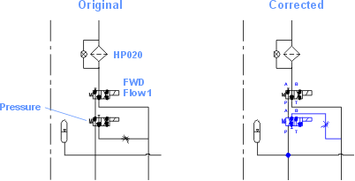
Page 20: The schematic does not show the high pressure filter after component 1 (FWD Flow 2 valve) and the ball valve.
Page 20:
- The arrangement of the pressure valve seems to be incorrect. When the solenoid is energized the pressure line is bocked. Forward flow is not possible.
- The accumulator after the pressure gage cannot de-pressurize when everything is turned off. Yet it does.
The following diagram is believed to be correct.
System Modifications (Post Delivery)
2007 March/April: The D681-4718 proportional servovalves were replaced with model D671-3001. This impacts the manual as follows:
- p. 5, §1.4.1 is obsolete. Consult information pertinent to current servovalve.
- p. 22, Component No. 1 in Rotary Actuator Assembly Diagram should be replaced by D671-3001 (Moog.)
Last modified: 2007-04-23 Ross Wagner