| Common apparatus |
|---|
| Hydraulic system |
| Electronic components |
| Data acquisition |
| EMG monitoring |
| NLID Tools |
| Troubleshooting |
| Materials |
| Supine apparatus |
|---|
| Assembly procedure |
| Safety Measures |
| Components |
| Servovalve |
| Actuator |
| Potentiometer |
| Pressure Filter |
| Torque transducer |
| Boot |
| Literature |
| Computing resources |
|---|
| CVS |
| Ethics |
|---|
| SDS / Inventory |
|---|
Build a Simulink Block Diagram
Simulink Block Diagram
The first step in using the xPC system is to develop the code through the use of Simulink and the xPC Library of I/O blocks. The Simulink Block Library on the xPC Host machine (Spastic) includes the xPC library which has special blocks to interface with a variety of I/O boards.
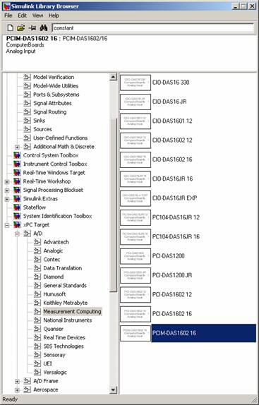 |
The screen shot left shows the library open to the Measurement Computing PCIM-DAS1602/16, which is the A/D board on the target (Renshaw). Add this block and others by dragging into the Simulink model. Using a combination of the xPC blocks and other Simulink blocks, we can come up with a simple proportional position controller. |
The completed block diagram, shown below, performs the control law:
8*(Desired Position - Actual Position - Initial Position)
The Sum, Gain and Constant blocks are standard Simulink blocks. From the DSP Blockset, a Sample & Hold and 2 delayed Switches are used to store the initial position.
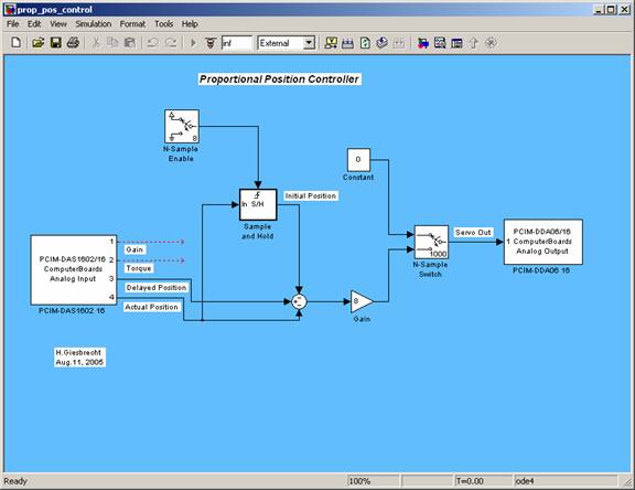
Link to model file: Proportional Position Controller
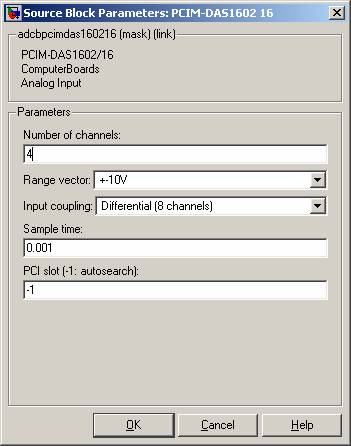
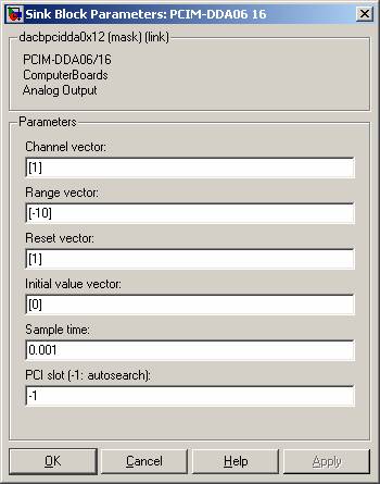
The I/O block parameters are shown in the figures below. TIP: Pay particular attention to the sample time and the range values. The sample time should match the desired sampling frequency. In this case, it is set to 1 kHz. The PCIM-DAS 1602/16 has been set up to run 8 differential channels, whereas the block default sets it to 16 single-ended channels.!
 |
 |
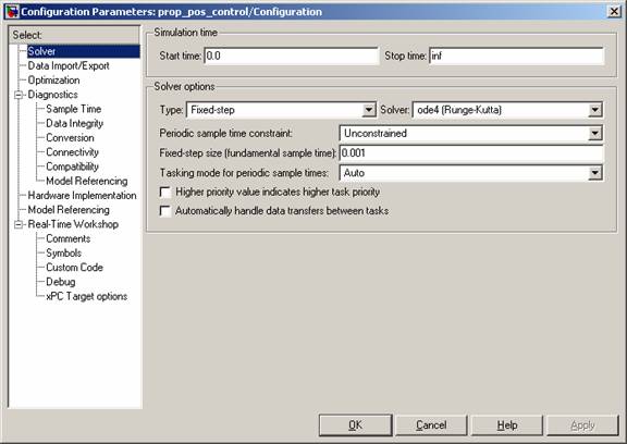
The next step is to set the Simulation Parameters, which can be accessed through the Simulation menu or Ctrl-E.
- The stop time can be pre-set or can run infinitely.
- The solver should use a fixed-step size (the Real-Time Workshop will not compile a variable-step simulation.)
- The step size should be the same as the sample times entered into the block parameters.
Now, you can build and load code to Renshaw.