| Common apparatus |
|---|
| Hydraulic system |
| Electronic components |
| Data acquisition |
| EMG monitoring |
| NLID Tools |
| Troubleshooting |
| Materials |
| Supine apparatus |
|---|
| Assembly procedure |
| Safety Measures |
| Components |
| Servovalve |
| Actuator |
| Potentiometer |
| Pressure Filter |
| Torque transducer |
| Boot |
| Literature |
| Computing resources |
|---|
| CVS |
| Ethics |
|---|
| SDS / Inventory |
|---|
Valve Drive Module
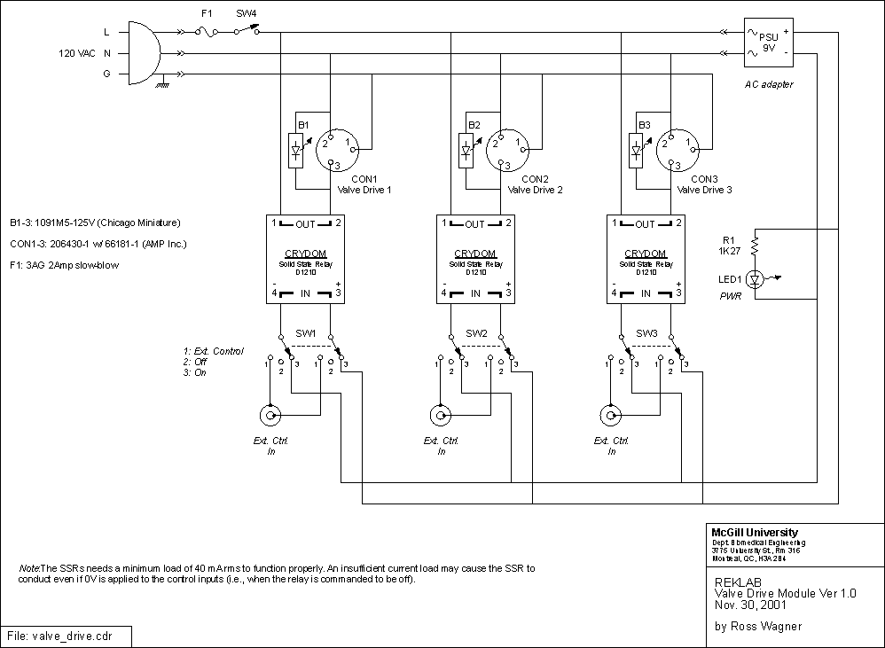
This schematic also available as:valve_drive.cdr (v.9), valve_drive.pdf
Components
- D1210 Solid State Relay (Crydom)
- 1091M5-125V LED Indicator light (Chicago Miniature)
- K-RM-178-BK Chassis (Pactec)
- 206430-1 Circular Plastic Connectors with 66181-1 socket contacts (AMP Inc.)
Click
Functional Description

This module supplies 120VAC power to the solenoid and directional valves used to direct fluid flow through the hydraulic system. Each valve-drive section (3 in all) supplies power as determined by its own selector switch. The user may manually turn a valve on/off or put it under electronic control via the "Ext. Ctrl. In" BNC connector. In this latter case, a TTL signal may control the valve drive; a high level will turn the drive on. The pilot light will illuminate when the valve is being powered (see Note 1 below).
This module interfaces with the hydraulic system as follows:
For Valve Drive section 1:
- Connect Ext. Ctrl. In to the Logic Module FWD FLOW 1 output.
- Connect Drive Out to the input of valve FWD Flow 1.
For Valve Drive section 2:
- Connect Ext. Ctrl. In to the Logic Module PRESSURE output.
- Connect Drive Out to the input of the pressure valve.
For Valve Drive section 3:
- Connect Ext. Ctrl. In to the Logic Module FWD FLOW 2 output.
- Connect Drive Out to the input of valve FWD Flow 2.
Note:
The solid state relays within the module require a minimum load to shut off. If, for example, no valves are connected to the module then powering it on will cause all of the pilot lights to illuminate regardless of the position of the selector switches. In this case, however, the light intensity is significantly less than when a valve is connected and is turned on.
Last modified: February 18, 2002 Laura Galiana