| Common apparatus |
|---|
| Hydraulic system |
| Electronic components |
| Data acquisition |
| EMG monitoring |
| NLID Tools |
| Troubleshooting |
| Materials |
| Supine apparatus |
|---|
| Assembly procedure |
| Safety Measures |
| Components |
| Servovalve |
| Actuator |
| Potentiometer |
| Pressure Filter |
| Torque transducer |
| Boot |
| Literature |
| Computing resources |
|---|
| CVS |
| Ethics |
|---|
| SDS / Inventory |
|---|
Anti-Aliasing Filter Bank
Block Diagram
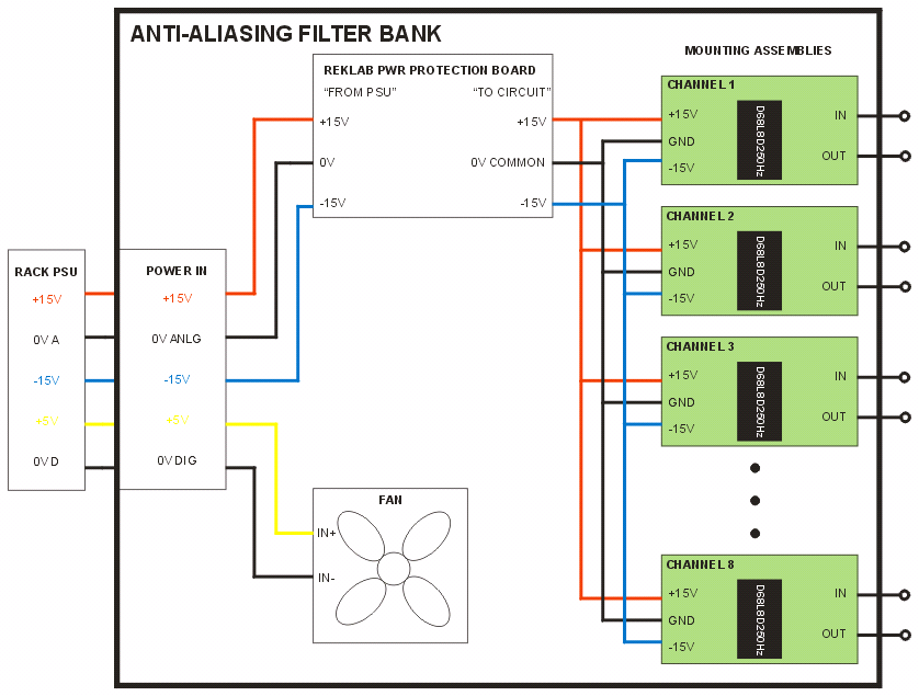
The above diagram is available in PDF format and in the original CorelDRAW 9 format.
Components
Parts List (Excel)
D68L8D250HZ
INA114
LT1007
ECH-S1H103GZ Capacitor
ECH-S1H102GZ Capacitor
KDE0504PFB2-8, DC Fan
Functional Description
This module consists of 8 independent analog filters built on mounting assemblies shown to the right of the block diagram. Each filter channel realizes an 8-pole, 6-zero constant delay transfer function with unity gain, cut-off frequency of 250 Hz, and a stop-band attenuation of 80dB.
Ideal filter characteristics
Filter transfer function
MATLAB function to create filter transfer function
Schematic of Mounting Assembly
This schematic is available in PDF format and in its original PCB 123 format.
Circuit Description
The filter measures the input voltage differentially via instrumentation amplifier U2. The in-amp gain G = 1+ 50k/R6 and is unity since R6 = infinity. R7 and R8 prevent the output of U2 from hitting the rails when the input (at J2) is not connected to a source by providing dc paths to ground for the input bias currents. R9, R10, and C6-C8 form a lowpass filter to attenuate RF input noise so that U2 does not internally rectify the noise and produce an erroneous output. The input filter has a differential and common-mode bandwidth that has been set to 4 kHz and 85 kHz, respectively. Information on RF filter design may be found in this reference.
The output of U2 is fed into the U1 which is a commercially produced active filter made by Analog Devices and is what predominantly sets the filter channel frequency characteristic. The dc output offset of U1 is trimmed via R5.
The output of U1 is fed into op amp U3 which is configured as a non-inverting amplifier. The gain of the amplifier G = 1 + R2/R3 and is unity since R3 = infinity. R1 and C5 stabilize the amplifier and allow U3 to drive a capacitive load of at least 3 nF (experimentally determined.) This capacitance is equivalent to ~100 feet of coaxial cable. R4 protects U1 in case of a fault in U3. (U3 has compensated input bias currents and so does not require an external compensating resistor.)
Trimming the active filter module:
Trimming potentiometer R5 is not to be used to zero the dc offset of the system output (at J1); it should be used only to zero the offset produced in the D68 filter module. To zero the output:
- With the power off, remove U2.
- Use a thin wire to jumper pins 5 and 6 in the IC socket. (This applies 0V to U1’s input.)
- Apply power to the filter box and let the electronic warm up for at least 5 minutes.
- Trim R5 until the voltage at pin 17 reads 0V.
- Power down the filter box.
- Remove the jumper and insert U2.
Fan Selection
The fan selected was a Sunon Inc. 5 VDC Brushless fan which produces 6.2 CFM of air flow. The manufacturer’s datasheet for the fan can be found here.
An explanation of fan sizing can be found in the following MS Word or PDF documents. The theory on fan selection can be found on the Sunon Inc. website. (See references below.)
Theoretical Filter Response
The effect of the RF filter on the system performance may be investigated using the MATLAB function found here. Simulation results are presented below.
The theoretical group delay and step response resulting from the D68 module and the D68 module + RF filter (cascade) illustrates that the effect of the RF filter on the system is minimal.
Experimental Filter Response
A typical system step response measured on an oscilloscope is shown below.
Step responses for all channels may be found in this PDF
file. 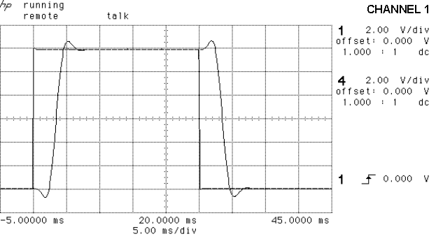
A typical frequency response measured on a dynamic signal analyzer is shown below. Frequency responses for all channels may be found in this PDF file.
Printed Circuit Board
The above diagram is available in PDF format and in its original PCB 123 Schematic format.
The mounting assembly is a variation based on the FMA-01S Single Channel Filter Mounting Assembly by Frequency Devices.
Details of the REKLAB Power Protection Board will be found in the Electronic Components of the on-line manual as this board is used in several other modules.
Comments on Filter Selection
For the sake of discussion the effects of the RF filter will be ignored. Doing so yields a worst-case scenario since the filter further attenuates the input.
These anti-aliasing filters are used in conjunction with a sampled control system running at 1000 samples/second – which yields a Nyquist rate of 500 Hz. Ideally, one would like for the Nyquist rate to be at the start of the filter stopband, but this is hardly the case. The filter gain at Nyquist is a mere -29 dB which theoretically permits a significant amount of aliasing to occur. We nevertheless can use these filters as anti-aliasing filters because of the following observations:
(i) For the types of experiments conducted in the lab both position and torque signals contain 95% of their power in the bandwidth of 0-100 Hz.
(ii) The hydraulic actuator (at least on the supine setup) shows no significant response to noise of bandwidth 100-500 Hz superimposed on the actuator command signal. (Tests were conducted with filtered white noise having 6Vpk-pk amplitude.)
(iii) Though EMG signals contain 95% power in the bandwidth 0-400 Hz, any use of EMG signals inside of the controller would be heavily lowpass filtered in order to provide the subject with visual feedback information. Hence, within the controller there is no need to represent EMG signals with frequency content exceeding 100 Hz.
With the above in mind, it suffices to select an anti-aliasing filter that minimizes aliasing in the frequency band 0-100 Hz.
With the above specified sampling rate, an input signal of 900 Hz aliases to 100 Hz. The filter gain at 900 Hz is less than -80 dB, which is better than the filter stopband gain. Input frequencies above 900 Hz will be attenuated even further.
The constant delay filter has approximately 6% overshoot in its step response which gives it less than ideal dynamic characteristics. (Ideally one would like a monotonic step response.) Though an 8th order Bessel filter has a better step response, the slower attenuation rate provided by this type of filter prohibited its use. A lower cutoff frequency than that required for the constant delay filter is needed to meet the attenuation requirements at 100 Hz. The penalty incurred by this is a longer group delay which limits the closed-loop frequency response of the actuator with the simple control law being used.
References
C. Kitchin et al., “Input filter prevents instrumentation-amp RF-rectification errors”, EDN Nov. 13, 2003, pp. 101-102.
Sunon Inc., “How to select the right fan or blower”, www.sunoneurope.com.
Last modified: June 7, 2006 Baher El-Sakkary